- Supports high heat resistance and high withstand voltage required for xEV and Industrial devices
- Support in reduction of PCB board size due to reduced creepage distances by excellent tracking resistance
- Halogen-free material reducing environmental impact
Circuit Board Materials
- Part Number
- Application
- Detailed use


・Industry
EV Charging Stand, HV Control Unit, PV Module
New part number *
Laminate R-356AD
Prepreg R-355AD
Laminate R-356YD
Prepreg R-355YD
* UL certification products
Properties
(R-356AD*¹, R-356YD)
(R-356AD*², R-356YD*³)
(1000V)
The sample thickness *1: 0.8mm or less, *2: 0.8mm, *3: 0.63mm or more
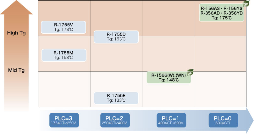
Positioning of R-356AD, R-356YD
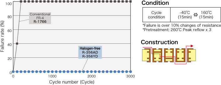
Through-hole reliability
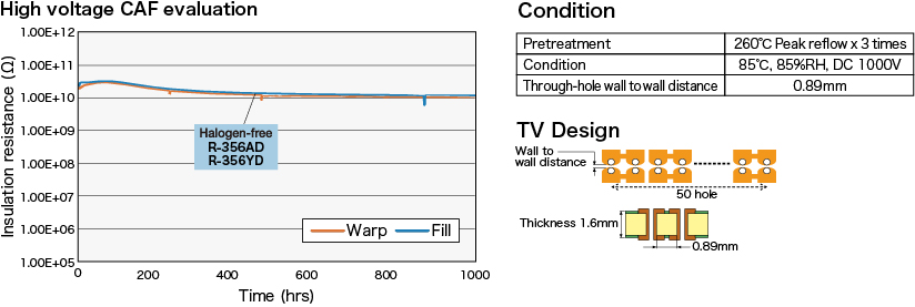
Insulation reliability
General properties
| Item | Test method | Condition | Unit | Halogen-free R-356AD | Halogen-free R-356YD | Our conventional Halogen-free R-1566(W) | |
| Glass transition temp. (Tg) | DSC | A | °C | 175 | 148 | ||
| TMA | 170 | 145 | |||||
| Thermal decomposition temp. (Td) | TGA | A | °C | 355 | 350 | ||
| T288 (with copper) | IPC-TM-650 2.4.24.1 | A | min | 10 | 3 | ||
| CTE z-axis | α1 | IPC-TM-650 2.4.24 | A | ppm/°C | 40 | 40 | |
| α2 | 180 | 180 | |||||
| RTI | UL Method | C-48/23/50 | °C | 150*¹ | 150*² | 130 | |
| PLC | – | 0*³ | 0 | 1 | |||
| Peel strength | 1oz (35µm) | IPC-TM-650 2.4.8 | A | kN/m | 1.6 | 1.6 | 1.8 |
| Flammability | UL Method | C-48/23/50 | – | 94V-0*³ | 94V-1 | 94V-0 | |
The sample thickness is 0.8mm.
*1 Thickness is 0.8mm *2 Thickness is 0.63mm or more *3 Thickness is 0.8mm or less
Our Halogen-free materials are based on JPCA-ES-01-2003 standard and others.
Contain; Chlorine:≤0.09wt%(900ppm), Bromine:≤0.09wt%(900ppm),
Chlorine+Bromine:≤0.15wt%(1500ppm)
The above data are typical values and not guaranteed values.
 For your study !
To extend the cruising range of a BEV or to improve the power output of an Industrial Device, SiC and GaN semiconducters are used for related electronic components like DC/DC converter or Inverter. Those devices are able to work at higher voltages and also higher temperatures. On the other hand, the reductions of size and weight are common topics on every automotive part.
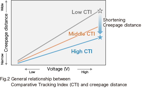
The CTI (comparative tracking index) and the RTI (Reference Temperature Index) are important base material characteristics to support such market trends.
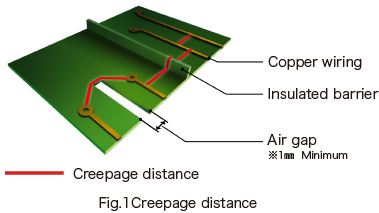
Relationship between creepage distance and CTI
Relationship between RTI* and MOT
Materials inside this class are showing a max. RTI of 150°C.
If the final equipment has to fulfil a MOT (Maximum Operation Temperature) of 150°C, you must use Highly heat resistant materials with a minimum RTI of 150°C.
* RTI (Relative Thermal Index)
An indicator of the ability of a material to retain certain physical properties (physical, electrical, etc.) when exposed to high temperatures for extended periods of time.
The material has excellent tracking and heat resistance. This material is suitable for various applications that require high voltage and downsizing, such as automotive and industrial applications.